

Moshe Bril, Holo/Or Ltd.
Perforated thin sheets of material are required in many applications, including plastic and metal sheets in the packing industry, cartons and metal foil that enable easy tear-off, filters for cigarettes, tubes for liquid or gas drainage, and preweakening of metal sheets for automobile air bags.
The basic setup in laser perforation includes a pulsed laser, a lens and either a moving mirror, a rotating web or both. Each laser pulse creates a hole in the material. During the blank time in which there is no pulse, either the sheet can be moved or a mirror can redirect the beam. Laser perforation provides high throughput and accurate positioning without leaving any working residue on the material and it is replacing mechanical perforation machines in many applications.
Fig. 1: Laser perforation creates uniform designs.
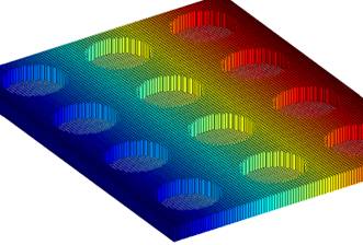
Laser perforation systems need to reach high throughput, keep a small footprint and create accurate and clean holes at a well-defined pitch. The system performance can often be improved rather easily by including a single diffractive beamsplitting element. This is especially true for applications in which the system needs to burn a large number of holes in a thin layer.
Operation principal
Beam splitters duplicate a master beam into the requested number of beams, which are positioned in a one- or two-dimensional array at well-specified angles. The input diameter equals the output diameter for each duplicated beam (Figure 2).
Fig. 2: Basic operation
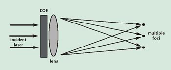
The beamsplitter enables simultaneous perforation of a number of holes in the same part with an extremely accurate distance between the spots. The locations of these positions are aligned in respect to each other; this cost-effective element provides greater throughput, speed and better alignment, and often removes the need for a moving X-Y table.
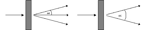
The beamsplitter accepts as input a collimated beam at nominal incidence angle and produces, at various angles, a number of collimated beams. These can be transformed to spots by a focusing lens. If this lens is placed close to the element, it can focus all the beams. The separation angle for double- and triple-spot beamsplitters is defined in Figure 3.
Fig. 3: Definition of separation angle.
Typical setup
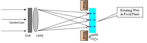
A typical setup includes a pulsed laser, a diffractive beamsplitter or optical element (DOE), a focusing lens, an optional mask and a rotating web.
The laser generates a pulse at a fixed repetition rate, while the beamsplitter creates a well-defined amount of high-intensity beams. The lens turns these beams into spots in its focal plane. A rotating web carries a sheet of material that will be perforated at a specific amount of positions for each laser pulse. The low-intensity minor spots/beams can be masked by a beam stop, keeping the edges of the sheet clean.
Characteristics
The diffractive beamsplitters have the following features:
• Accurate angle separation that translates into an accurate pitch or hole-to-hole distance.
• Intrinsic alignment, where all the work is done by a single diffractive pattern on one surface of an optical element. As a result, the angle separation does not depend on the alignment of two or more discrete components.
• High power threshold. The typical element consists of pure fused silica or ZnSe with high power thresholds.
• Power uniformity. The uniformity between the spots can be very good (±1 percent for 1 × 2 and 2 × 2 splitters), but significantly more for other designs. We recommend asking the manufacturer what uniformity can be expected for a particular element.
• Optional Ar/Ar coating. This reduces the back reflection and increases efficiency.
• Insensitive to X-Y-Z displacement, the spots will keep their position even if the beamsplitter changes its X-Y-Z position.
• Rotation. The spots will rotate along with the part.
Design considerations
Depending on the design, up to 20 percent of the energy will be directed to a number of weak, well-defined positions. Each position may receive about 5 to 10 percent of the energy in the strong spots. This amount depends on the design. We recommend asking the manufacturer what uniformity can be expected for a particular element.
Using a metal mask that stops the light before it hits the well-defined position (Figure 4), can eliminate any negative effect these low energy spots may have. At Holo/Or we provide information on where these positions are located for each design. We also offer low, zero-order splitters that come with an extra low amount (<0.5 percent depending on design) of energy in the unwanted zero order in the center.
Fig. 4: Typical setup
Beam splitters send about 20 percent of the energy outside of the spots to well-defined positions, depending on the design. This can create warming. The refractive index of material changes a bit with the increased temperature, and the focal length of the optics changes accordingly. This effect normally becomes substantial only when the temperature of the optical elements reach 80 °C or higher. These temperatures typically will only be reached with powerful lasers or as a result of poor ventilation of the lenses. There are two ways to implement solutions to overcome this problem: The first is to improve the ventilation of the lenses with airflow. The second is to design the optics to operate well at the higher-equilibrium temperature.
The beam splitting are insensitive to X-Y-Z displacements but are sensitive to rotation. Typically, parts are aligned with a trial-and-error method (e.g., burn some thermal paper; if not well-aligned, rotate the part accordingly). A more elegant method is to order an intrinsically well-aligned part with 1×1 mm notches. These can be made with an accuracy of about 0.1 degree with the rotation axis.
For applications in which the weight and footprint of the system are essential, we can supply a single element that is both a focusing lens and a beamsplitter.
In addition to the energy directed to the main beams, a small part of the energy will be directed toward well-defined angles. The uniformity and efficiency depend on the design. Performances for selected designs are listed in Table 1.
Typical Performance selected designs
| Element Type |
Energy in desired beams |
Angle Accuracy in mRad |
Uniformity between beams |
Energy in the original beam (zero order) |
Energy in strongest single unwanted angle |
|
2 Spot |
79% |
0.02 |
+/-0.5% |
<1% |
4.5% |
|
3 Spot |
84% |
0.02 |
+/-5% |
28% (desired) |
3.2% |
|
9 Spots |
75% |
0.02 |
+/-5% |
11% (desired) |
4% |
|
15 Spots |
85% |
0.02 |
+/-5% |
6% (desired) |
1% |
Selection of Standard Beam Splitters:
|
|
Refractive substrate |
Incident beam parameters |
Spot Separation if used with |
||||
|
Part No. |
Type |
Material |
Dia. |
Wavelength |
Angle Separation |
f=50mm |
f=100mm |
|
Inch |
in mm |
In degrees |
in mm |
||||
|
DS-002 |
Double-spot |
ZnSe |
1.1″ |
10.6 |
2.7 |
2.36 |
4.72 |
|
TS-004 |
Triple-spot |
ZnSe |
1.1″ |
10.6 |
1.35 |
1.18 |
2.36 |
|
DS-006 |
Double-spot |
Fused Silica |
1.0″ |
1.064 |
2.53 |
2.21 |
4.42 |
|
TS-3053 |
Triple-spot |
Fused Silica |
1.0″ |
0.532 |
2.5 |
2.18 |
4.37 |
|
MS-022 |
Splitter 15 |
Fused Silica |
1.0″ |
1.55 |
0.041 |
0.04 |
0.07 |
[elementor-template id=”21997″]