Binary Elongated Focus (EF) element is a unique diffractive element. Its functionality is limited to a small extension of focus, but for certain application (for example in microscopy and in micro-material processing) it can be of vital importance.
Passive elongated focus elements can replace the need for a complex dynamic opto-mechanical device or distribute laser energy in depth more efficiently for material processing.
Due to the “gentle” effect, the effect will be felt only with single mode lasers with precision diffraction limited optics. For multimode sources or optical systems with large amounts of aberration, focus extension will be negligible. For stronger focus elongation, we suggest our multilevel solutions.
The depth of focus can be defined by the following formula:

- ZRx is Raleigh length
- M2x is beam quality factor for x-axis
- d is the beam diameter at e-2
- Δ – is the energy density drop
This formula is correct for classical spherical lenses. Diffractive optics allows one to break down this limitation.
In the following simulations, we will compare the profile of a single mode laser TEM00 with and without using an EF element, followed by an analysis of the results.
Figure 1. Simulation of XY plane. The Red line depict the theoretically calculated Diffraction Limited (DL) spot size for a specific EFL, and the white line depicts the elongated focus spot size at exp-2, calculated from simulations. Intensity isn’t normalized.
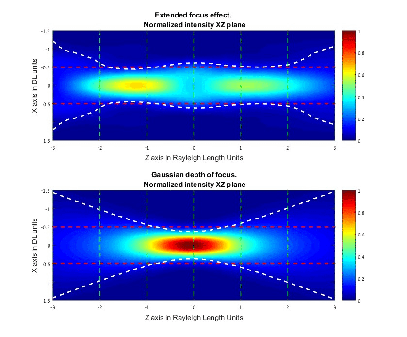
Figure 2. Intensity profiles
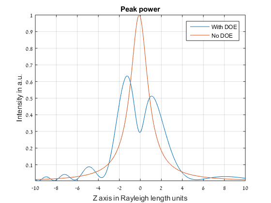
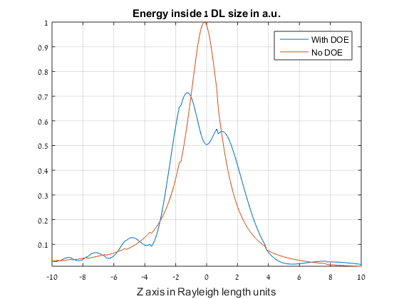
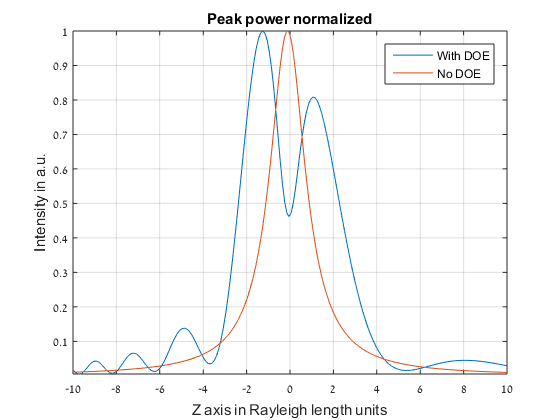
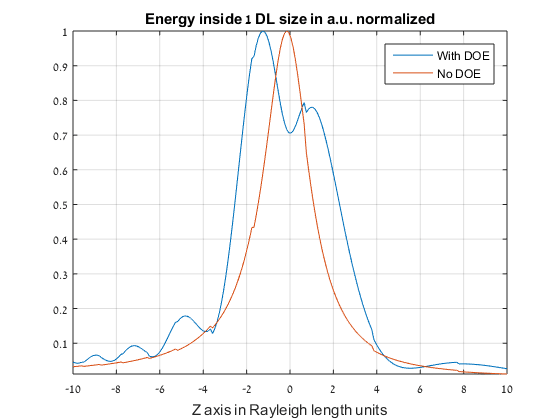
Figure 3. Beam size along optical axis
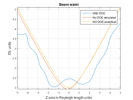
Figure 4. Longer region for analysis
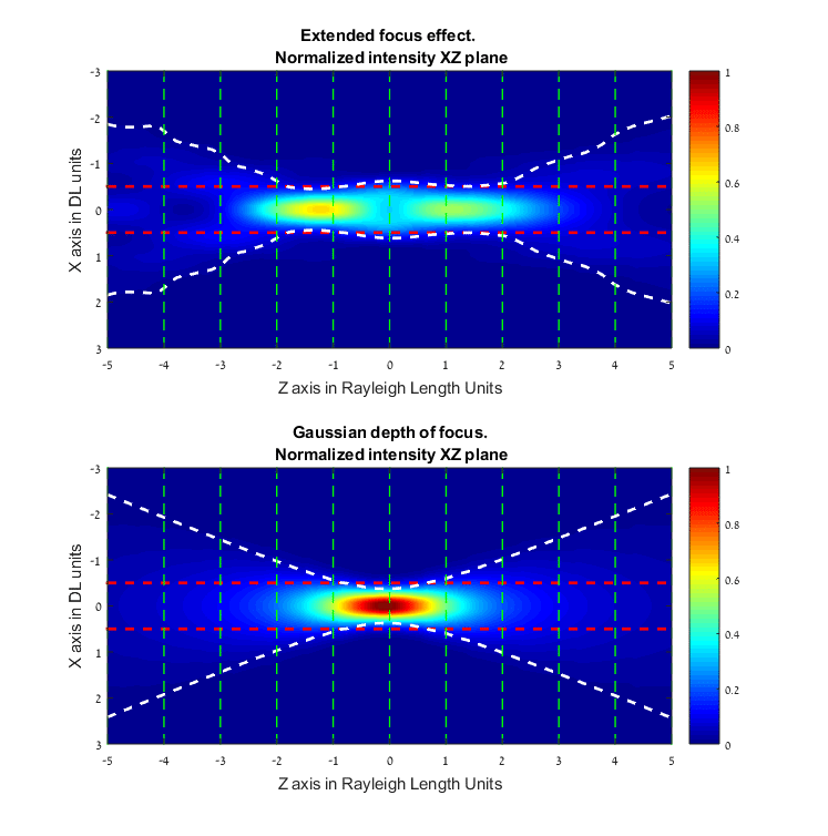
Analysis of the Binary EF element
-
Binary EF element separates one focusing region into two regions with an intermediate zone that look like a kind of saddle point. By reducing the beam size it is possible to narrow the saddle point region up to the point where the functionality of DOE will be eliminated. By increasing beam size saddle point region will widen up to until its local minima will achieve zero intensity and then the functionality will be very similar to a bifocal element.
-
From figure 4 we can see a difference between waist diameters with and without using EF. The summary of waist diameter for different positions along optical axis in units of Rayleigh length shown below:
Distance from focus(Rayleigh lengths) 0 -1 -1.5 -2 -3 Waist size With EF 1.4DL 1.1DL 1.0DL 1.3DL 2.6DL Waist size without EF 1.0DL 1.3DL 1.7DL 2.1DL 3.0DL Ratio of with EF/without EF 1.4 0.84 0.58 0.62 0.87
-
From figures 4 we can see that after 3-4 Rayleigh lengths the two cases have a similar behavior. The difference in beam size becomes almost constant. The distance range of > 4x Rayleigh lengths is out of region of interest because energy density there is very low.
-
From figures 2 and 3 we can see the reduction in efficiency caused by the DOE. The efficiency of the binary EF is about 90%. The peak power and energy enclosed in a certain diameter are also reduced. Reduction of peak power is more significant than encircled energy. This can be important to processes that depend on a relatively high threshold.
-
In figures 3 and 4 we observe that the steepness of the beam diameter change is higher for the EF element.
-
In figure 4 (among others) we can see that the regions before and after the main focal length (EFL) aren’t symmetric. This is typical for EF elements.
-
In figure 4 there is a slight difference between the analytical line of Gaussian and the beam size from simulation, especially for the range before EFL. We assume that this is a numerical error of the propagation method we used.


